Brose Vollmatrix
Posted on Tue 26 August 2014 in projects
The beginning
Let's say it's the beginning of December and you lurk on eBay trying to find something to spend your time with while everyone is with their family on Christmas. And suddenly you stumble over this gem:
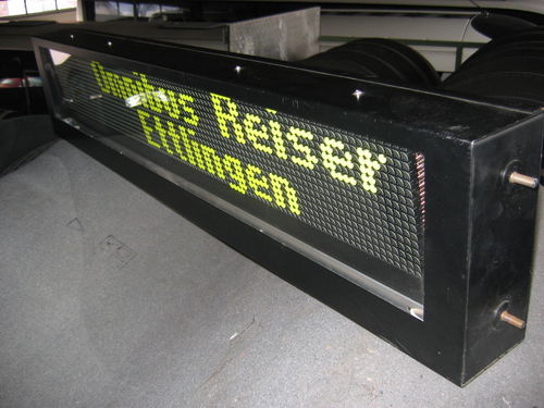
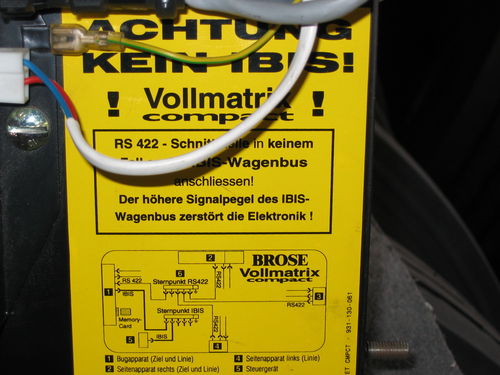
I thought to myself: that would look nice in my livingroom. So i bought it.
The Waiting
While I waited for the package to arrive, I kept my self busy searching information about the display. There was none, only some rare information about the IBIS-Wagenbus, but the label on the back of the display stated that it's not compatible with it.
The Waiting(pt.2)
The Display arrived -- kind of. I've missed the postman and so I've found myself carrying this 25Kg package from the next post office home (no, I don't own a car).
So there it was, and I realized that I had no suitable power supply. So again, waiting...
This time more productive.
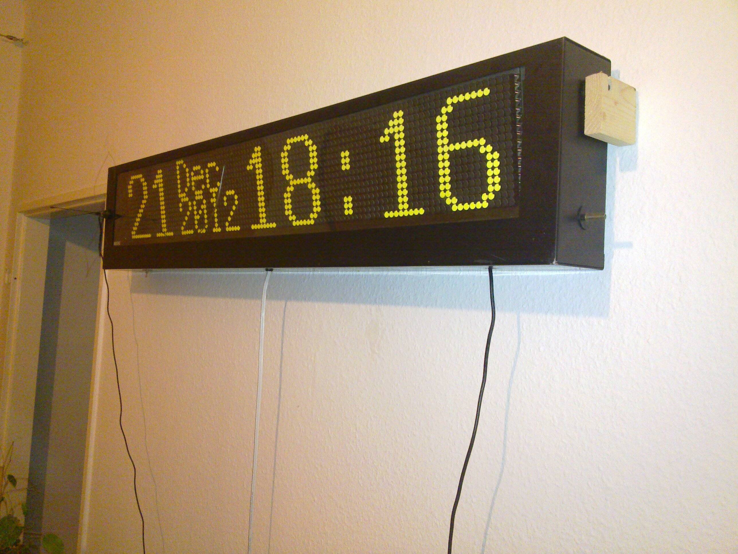
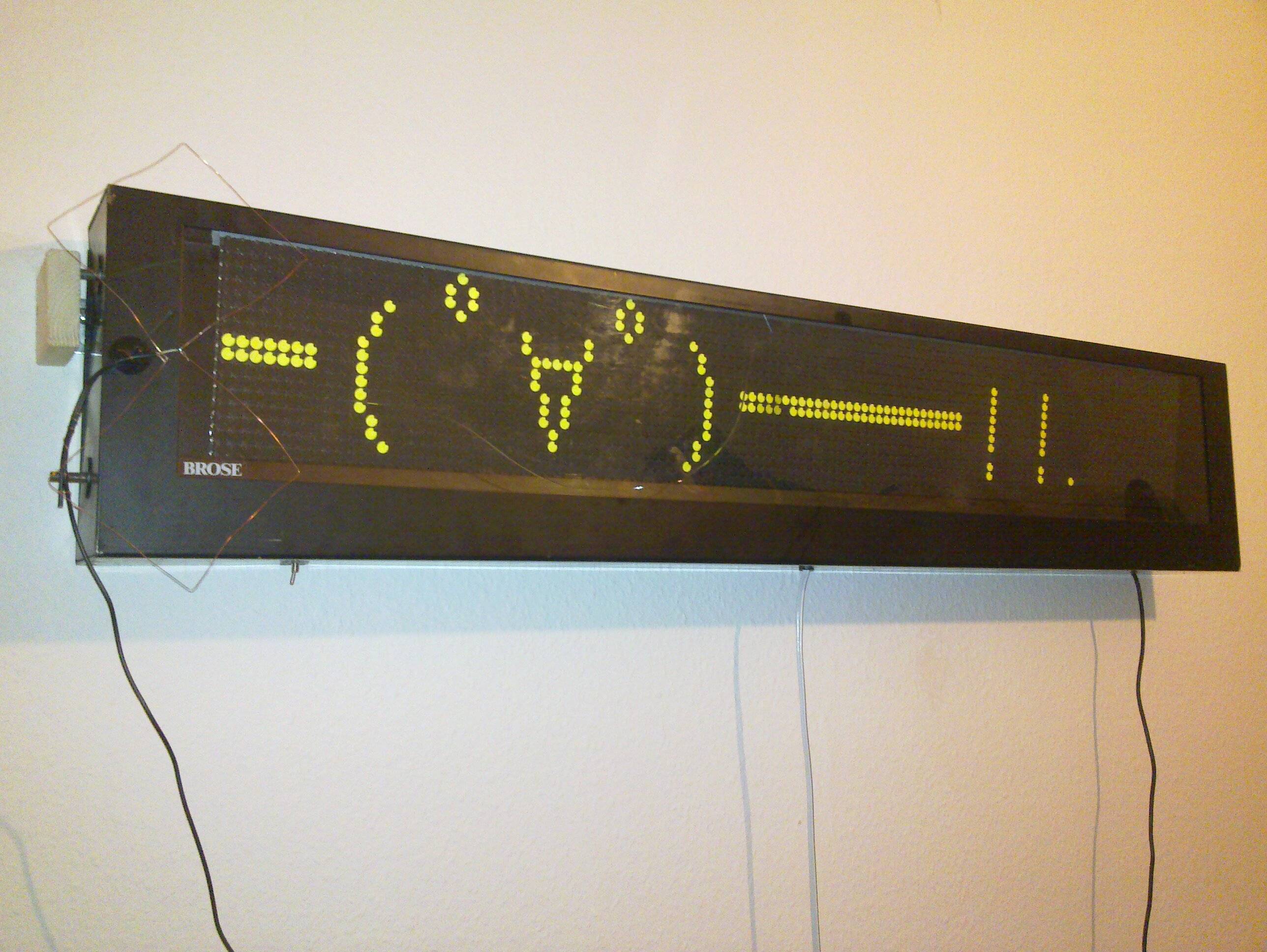
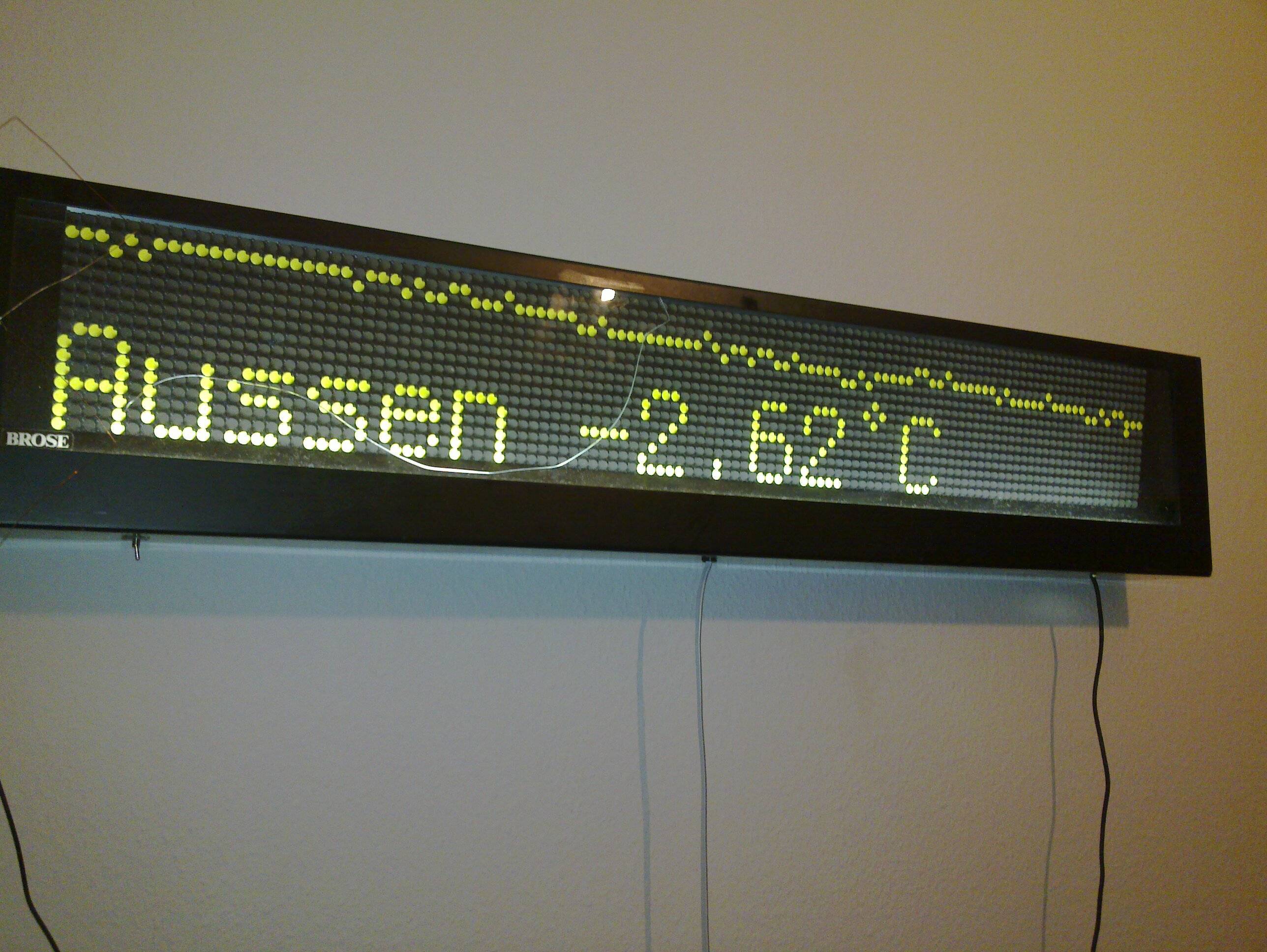
Some impressions:
The Display
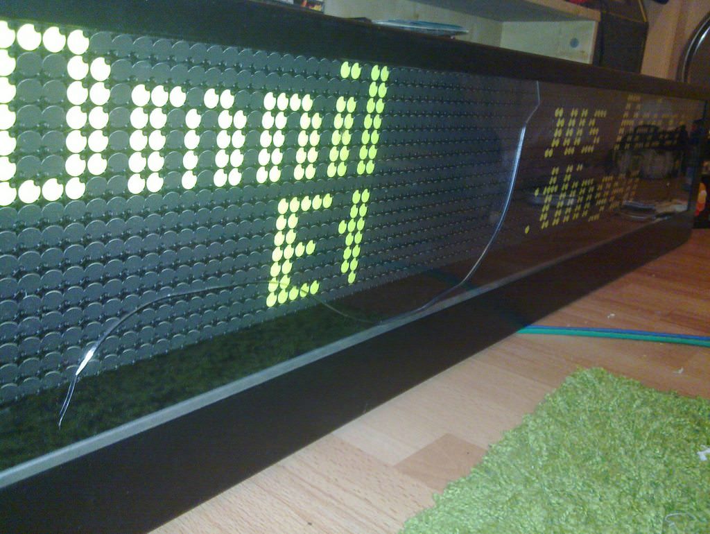
Controller on the back of the display
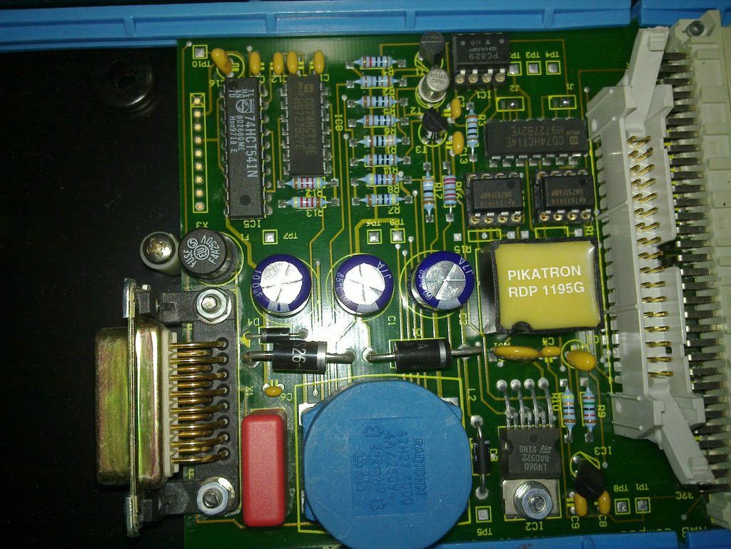
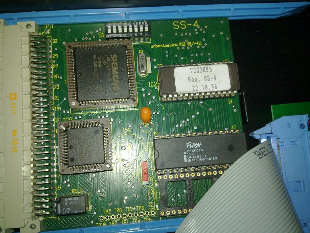
Inside the display
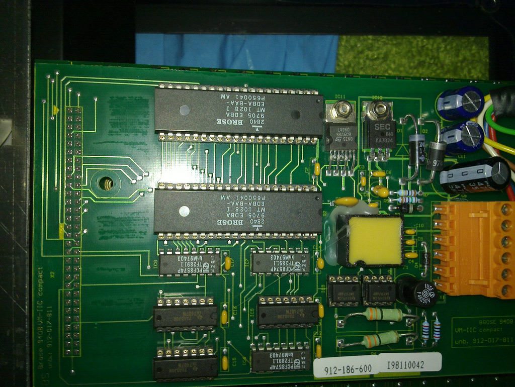
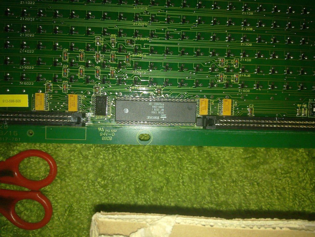
There are two DIP8 ICs on the right side of the controller, these are two SN75176B RS422 transceivers. Pin 1 of the two ICs are connected to PIN 14 and 15 of the PCF8574P I²C portexpander(that could have saved me ~2h of tinkering around later)
ACT2 - Reverse Engeneering
There are two ways to guess the protocol between devices first: READ THE F[amily friendly Content] DATASHEET and the second is to assume that its some kind of UART and hook up your logic analyzer and guess the Baudrate(which i did) These were the results:

Note to self: get a better logicanalyser, the buspirate isn't that good.
Channel 1 and 3 were connected to PIN 1 of each of the tranciever ICs. I failed hard in getting a clue what kind of protocol that is, because i've never seen I²C under a scope. Finally after 2 hours and almost giving up i've read the datasheet and found that PIN 14 and 15 are the SDA and SCL lines of the I²C Portexpanders.
Now that that is out of the way, I had a way to communicate with the display.
So i've hooked my Bus Pirate up to the SDA and SCL lines and put it into I²C-Sniffing mode and made it show something.
the result was this: Gist#4382522
These are the I²C-Commands send by the Controller on the back of the display to the controller on the inside.
I've noticed some pattern:
And after replaying these 5 commands I had my first success: a Pixel on the Display flipped.
To get a clue how to address each pixels i've wrote a small python script which showed me the status of each pin after each command.
Because the controller sends only pixels that are actually need to change i took 2 Different Dumps one of them shows "Dienstfahrt" on yellow background and the other one "HEEPEN Süd" on black Background Gist#4340341 and this is the output of the script Gist#4387579.
So basically this is what the output pins on the portexpanders look for each pixel
| row | col | 0x42 | 0x40 | 0x44 |
|---|---|---|---|---|
| 0 | 28 | 00100000 | 11111101 | 01110010 |
| 1 | 28 | 00100000 | 11111101 | 01110001 |
| ... | ||||
| 19 | 28 | 10100000 | 11111101 | 11010010 |
| 0 | 29 | 00010000 | 11111101 | 01110010 |
Note that the Controller is actually sending 20 pixels per column even though the Display has only 16 rows
** TO BE CONTINUED **
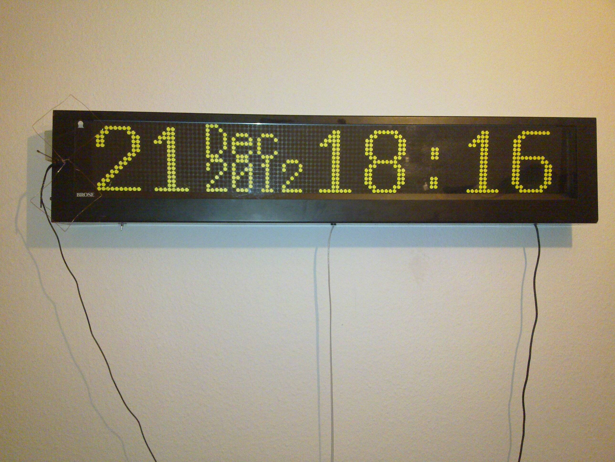
How not to Build an USB-Device
So i had the Display on my Wall and everything working fine, except for my Bus Pirate still being inside.
I've looked around on the internet for a piece of hardware that would fit my needs and found that: i2c_tiny_usb
Since i had a ATTiny85 lying around i was about to try this, but i've noticed some disadvantages:
- it uses the reset pin for IO and once flashed I could never flash it again
- I had no 12 Mhz Crystal lying around
- and I wanted to offload some of the code into the µC
I've remembered that it is possible to use V-USB with the internal OC so i've gone with that and threw it together with some Software I²C implementation I've found on the net. This all went pretty well for being my first µC project ever.
The result isn't the prettiest but it works and is quiet reliable
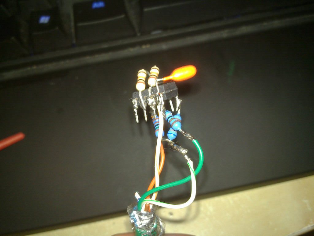
(Yep i know, i've broken almost every design rule with that, and i am even outside of the USB-Specifications with sending 5V on D+ and D-)
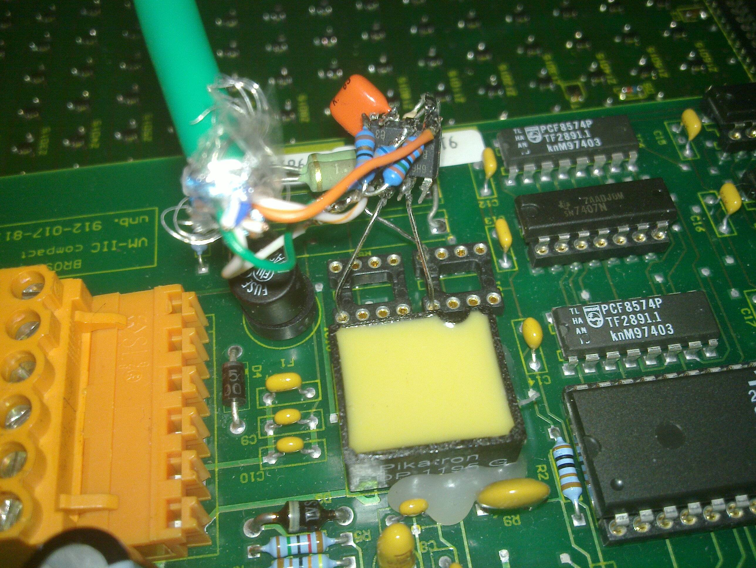
(The ground connector from the AVR is connected to the wrong pin, i fixed that before turning on)